1-1 Cable Chain Closed Type


Mounting bracket size
\
1-2 Brackets for closed type


1-3 Assembly method

2-1 Opened Cable Chain Snap-on Type

2-2 Dimensions for Snap-on Type
Series 1

Series 2

Length : fixed point in the middle - total length = stroke/2+ 3 (KR+G)
fixed point in the one side - total length = stroke + 3 (KR+G)
Model : To choose fit model, it's recommended 20% plus to the inside cable's outer diameter
Curve : To choose winding radius, it's recommended 8~10 times to the inside cable's diameter
2-3 Brackets for Snap-on Type

2-4 Product Series 1

2-5 Assembly method - Product Series 1

2-6 Product Series 2


2-7 Assembly method - Product Series 2

When assembling the cover, tilt the cover 45∘ to the connecting position and press it.

4-1 Chip Protection Closed Cable Chain

4-2 Dimensions for Chip Protection Closed Cable Chain

Body : reinforced plastic
Length : fixed point in the middle - total length = stroke/2 + 3 (KR+G)
fixed point in one side - total length = stroke + 3 (KR+G)
Model : To choose fit model, it's recommended 20% plus to the inside cable's outer diameter.
Curve : To choose winding radius, it's recommended 8~10 times to the inside cable's diameter.
4-3 Brackets for Chip Protection Closed Cable Chain

5-1 Snap-open chip protection Cable chain

5-2 Dimensions for Snap-open chip protection Cable chain


5-3 Dimensions for Snap-open Chip Protection Cable Chain


Cable Chain Design Specification
For unsupported application, KYEC cable chains achieve speeds in excess of 5 m/s and rates of acceleration of more than (10m/s). These guidelines apply to KYEC energy chains of every size if they are used " unsupported straight". In specific applications, the top speed is influenced and limited by the length of travel,additional load and the frequency of travel.
In order to estimate the service life of an unsupported application, all technical data must be provided: type and number of conduits, additional load, speed, acceleration, travel frequency and details of the technical environment. Wear of the energy chains is very low, due to a special material compound and plastic-oriented design. A service life of between 15-30 million cycles can be achieved for "unsupported straight" applications even in high speed application.
The maximum length of travel possible of an unsupported application depends on the stability of the chain used, and on the weight of the cables and hoses inside the chain (additional load). Figure 1 shows the maximum permissible " unsupported lengths with sag (FL)" of all KYEC cable chains depending on the additional load. Unsupported length is defined here in such a way that the upper section of the cable chain has a permission sag. In this case the upper section is bent over the back.
The largest possible travel is in any case equal to twice the largest possible unsupported length:
S max. = FLB*2
S max.= maximum travel
FLB= unsupported length with sag taking the additional load into account
The sag of the KYEC cable chains does not pose a problem in many applications. It may become critical however when acceleration and frequency of travel are very high. In such cases the cable chain may be additionally supported. Figure 2 shows the conditions for the application of the chains "unsupported straight". "Unsupported straight" means that the upper section hangs parallel to the lower section. This configuration permits maximum travel speeds, accelerations and bending cycles.


Guiding trough
Guiding trough are used for long travels, figure 3 is the basic shape. Height of guiding trough should be at least double to the height of cable chains.

Attention! The copper thickness and width is crucial for power rails selecting!! Some companies reduce the copper to lower the price in the same ampere rating power rails.
Actually, it sacrifices your safety and privilege. Less copper will make your equipment consume more energy and sometimes the overheat will cause the fire!!
| KYEC Safety Power Rails | |||||
| Type | Part number |
Capacity (A) |
Copper Thickness (mm) |
Copper Width (mm) |
Weight (Kg/m) |
| Three in one 75A | KY-AN3007 | 75 | 2 | 10 | 0.8 |
| Three in one 100A | KY-AN3010 | 100 | 2.8 | 10 | 1.03 |
| Three in one 150A | KY-AN3015 | 150 | 3 | 10 | 1.14 |
| Three in one 200A | KY-AN3020 | 200 | 3.8 | 11 | 1.42 |
| Four in one 75A | KY-AN4007 | 75 | 2 | 10 | 1.1 |
| Four in one 100A | KY-AN4010 | 100 | 2.8 | 10 | 1.4 |
| Four in one 200A | KY-AN4020 | 200 | 3.8 | 11 | 1.9 |
| Five in one 100A | KY-AN5009 | 100 | 2.8 | 10 | 1.7 |
| Six in one 75A | KY-AN6007 | 75 | 2 | 10 | 1.64 |
| Six in one 100A | KY-AN6010 | 100 | 2.8 | 10 | 2.06 |
Safety Power Rails
The safety power rails are electrical conductors of various profiles that are used to provide electrical potential to moving systems along a path of travel which have 3-6 poles.
The safety power rails are available for a current load from 75A up to 200A mobile electrification technology for moving transpotation vehicles and equipment. Common application include: manufacturing robots, material handling system, hoist and cranes, automated storage facilities and retrieval systems.
Safety power rail systems are available in a variety of configuration depending on applications requirements. Enclosed conductor systems typically enclosed conductors in a protective conduit meeting safety standard.
General technical information
Full Load Current Table of 3 Phase Alternating
Check the steps below first to select the correct current (Amper) of safety power rails and current collector:
1. Calculate the total motor's Horse Power (H.P) required. (ex. 10H.P)
2. Make sure the rated voltage(A.C.) (ex. 220V)
3. Get the current data by checking the above conversion table.(ex.27 Ampere)
The safety current of safety power rails would perhaps be affected if the circuit temperature is over 35℃

Horse power= total kws/0.75; A=Horse Powerx3; (on the assumption 220V)
Total current [A.] x 1.25 = proper current
According to the ampere quantity, choose the type of safety power rail:
90A-200A : 3P-6P safety power rail
150A:I type safety power rail
120A 320A 500A 800A: W type safety power rail
3P、4P、5P、6P Installments Diagram
Step 1 Supports design

Remark:
(1) The lateral design installment recommened when a camber occurs to the 3~6P safety power rail assembly.
(2) The hanger clamps are supposed to be installed every 0.5 meter from the starting point of the turning.
(3) The 3~6P tension part for safety power rails must be installed at the place about 10mm higher than the hanger clamp.
This step prevents water from flowing to the power-in place along the safety power rails; hence the short circuit won't happen.
(4) The silica gel must be coated on the connected place of the power-in part and safety power railas weather protection.
(5) The 3~6P safety power rails are not suitable for outdoor usage or the place with high acid/alkaline environments.
Step 2 End tension & power in parts Remark: (1) Install one end on the ground then lift rail up to estimated location and install another.
Step 3 Hanger clamp

(1) Aim the hanger clamp with power rail and push up. (Below left diagram)
(2) Use a slotted screwdriver to dismantle the hanger clamp. (Below right diagram)


Step 4 End tension & power in parts *Install the end tension after the power rail is settled with the clamps

4-1 4-2


4-3 4-4

4-5


Step 5 Fix square bar/current collector
Remark:
(1)Fix square bar could be welded on the crane or screw used.
(2)Fix square bar’s angle is supposed to be mounted. One diagonal of the bar
must be parallel to ground and safety power rail, another is verticle.
(3)Length could be cut as demand.
(4)If carbon brushes worn, just replace a new one.


Current Collector Installation


Twin type current collector : Add one more V-shaped clamper
* Twin current collectors are choosed for undulated, rounded, or special profile.

3P Rail connector and middle power in
1. Cut off the PVC material at 35mm from the end of safety power rail.
2. Bend upward copper material in vertical 90∘angle.
3. Insert both sides of 90∘verticle angle safety power rail into middle power feeding and connect both sides by screwing up M6 inner hexagon screw bolt on U type copper connector.


I type safety power rail installment diagram
Step 1. Support Design
A. installment for I type in 30 meters B. installment for I type over 30 meters


Linear Case Curve Case


1. Distance of each hanger clamp must be under 0.5m in around type.
2. The way to pull up rail is use traverse table put on the saddle's beam, pull up the rail when crane moves.
(As the commentary picture no.3 shown in end cover)
Step 2 Length in 30M

Length over 30M

Step 3 Set & Hanger Clamp
Use tool to clip inward Plastic Clip and pull I-type Insulated Conductor Rails out together if necessary.
Middle power feed in
1. Cut off 80mm long of insulated material PVC in the middle of I-type Insulated Conductor Rails for supplying power.
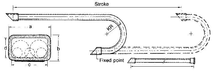
2. Contact Copper Conductor of I-type Insulated Conductor Rails by two piece of Copper Plate and fix it by M6 inner hexagon screw bolt.
3. Drill two holes Ø5mm through both Copper Plate and Copper Conductor of I-Type Insulated Cunductor Rails at the bottom and insert pins to connect and fix them.
Step 4 Set, End Tension & Power in
Step 5 Set, guide & Current Collector
Caution

(1) It is not allowed to incline over 15∘ when install I-type Insulated Conductor Rails.
(2) If I-type Insulated Conductor Rails Still incline after installtion, then it is required to adjust forcedly.
Part 1 Design


1. Structure Data

C30 C-rail Cross Section Chart C40 C-rail Cross Section Chart

2. Layout


3. C30、C40 Track Design Information
1.C30 Track Known Data
P=4 Single Trolley Capacity (Kg)
Iw=85 Length of Trolley (mm)
Z=11 Quantity of Trolley (set) Calculated: L=Z x Iw/1000= 9.3 (M)
※Cross-refer the chart---
Ia=1.3 C30 support clamp distance.

2.C40 Track Known Data
P=18 Single Trolley Capacity(Kg)
Iw=125 Length of Trolley (mm)
Z=10 Quantity of Trolley (set) Calculated: L=Z x Iw/1000= 1.25 = 10 x 125/1000= 1.25(M)
※Cross-refer the chart,
Ia=0.8 C40 support clamp distance.
Part 2 PVC Flat Cable

DESCRIPTION :

Part 6 Other Track and Trolley
1. Aluminum Track & Parts


2. Wire Trolley

3.ΙSteel Trolley

4. Produce On Demand

Part 7 Diamond Track (For Curve)
Flat Cable For Swerve Power Supply System

Application:

Dim.45 x 1.8L-100m
※Add a band will reduce the probability of cable broken.
Introduction:
The production of GlObe Star "W" type safe power rails is the results of a technological breakthrough.
Being specialized in hoist repair and related engineering innovation, we provide our customers with excellent services backed up by persistent devotion, responsibility and advanced technology. In order to overcome the difficulties that we have been confronted with during parts importing, we are delicating ourselves to the production and innovation of parts and components. Also, we have obtained numerous patents approved either by the ROC or overseas countries. We supply our customers with readily available engineering materials and technical assistance to shorten your preparation time.
Power Rails
Knowing the Germany has been using safe power rails since 1912 and bare conductor simply doesn't guarantee safety, we began to research, develop, and then mass produce 60-150 amp continuous rails, and have been highly recommended by our business partners.
We discovered that there are no high amperage power rails available on market, so we began to produce "W" type power rails with reference to German-made units.
With support and affirmation from our customer, we will continue our research and development work, offering our clients safe and automated engineering services.
Quanlity is a basic requirment for GlObe Star products.
Features:
Conductor
Made of aluminum and edged with stainless steel, the surface of this unit is erosion-resistant, and will not become oxidized. Can be used in a damp environment, ensuring good connection and durability.
With a "Λ" type contact surface, the brush can automatically correct its way as it moves forward on the rail. This type of surface maintains close contact, ensuring better electrical conduction. The lead angle of the conductor prevents the collector mount from tripping-out, enabling it to move more smoothly.
Connector
The connectors are featured with a reverse U-shaped guider design, strengthening the extension guiding of power rails. They stabilize the connection of the power rail conductors and avoid defective contact and voltage drop issues of the traditional 8-shaped connectors. The power rails are designed and improved with reference to equivalent German products, and they outperform similar products in the market.
Hanger Clamp
The hanger clamps are integrally formed with nylon resin, and can be easily installed by press bonding without use of screws.
Current collector
The two-armed current collectors are made of nylon resin with reinforced springs. Their structure is well designed for high performance and durability.
Carbon brush
The carbon brushes are well fabricated with materials from Japan and Germany, and undergoes laborious powder metallurgy and refinery process. Their conductivity and durability are outstanding.
Performance


▲ 800A ▲ 800A


▲ 500A ▲ 320A


▲ 320A ▲ 800A


▲ 320A / 500A ▲ 320A
※W型電軌工程實績用於台船、中鋼、台電、台灣車輛、台塑關係企業等。
General technical information
A. 交流三項發電機之全載電流表 Motor nominal currents

註:
1. 額定電壓為208V及200V者,可讓220V之相當值各增加百分之6及10的負載。
2. ※如功率因數為0.9及0.8者,左表有關數值應分別乘以 1.1及1.25倍。
3. 極數超過6極,及起動轉矩特別大者其全載電流大於本表支標準值 ,以據銘牌支標示值為準。
4. 採錄自電工法規P.514。
B. 相關技術資料較繁多,請來電再行寄上,謝謝。
C. 負載曲線 Current-carrying diagram for different duty cycle


備註: W500、W800入電位置不同時,再行調整用量
W型320A零件圖

1. 電軌本體 Insulated Conductor Rail KY-AW2030 (Copper inlaid)
KY-AW2032 (Stainless steel inlaid)

2. 電軌夾 Hanger Clamp KY-AW2100

3. 末端蓋 End Cap KY-AW2200
4. 接頭 Connector KY-AW2300

5. 接頭蓋 Connector Cover KY-AW2400

6. 電源接頭蓋 Power Feed Cover KY-AW2500

7. 定位夾 Anchor Clamp KY-AW2300

9. 雙臂集電架 Current Collector KY-AW2706
KY-AW2710

10. 絕緣棒 Towing Arm KY-AN1838 (380m/ml)
KY-AN1850 (500m/ml)

W型320A施工圖

1. Construction Design

A、立式施工圖 Vertical

B、側式施工圖 Side
2. Hanger Clamp Installation Diagram

3. Connector Cover and Power Feed Cover Installation Diagram
密合嵌入
4. Connector Installation Diagram

5. Anchor Clamp Installation Diagram
6. End cap Installation Diagram
7. Towing Arm and Current collector Installation Diagram
W型500A零件圖 (停產,只提供舊客戶更換零件)

1. 電軌本體 Insulated Conductor Rail KY-AW5050

2. 電軌夾 Hanger Clamp KY-AW5100

3. 接頭 Connector KY-AW5300

4. 接頭蓋 Connector Cover KY-AW5400
5. 定位夾 Anchor Clamp KY-AW5600
6. 末端電源接頭 Power Feed Connector KY-AW5301
7. 末端電源蓋 Power Feed Cover KY-AW5500

8. 雙臂集電架 Current Collector 200A KY-AW2720
9. 絕緣棒 Towing Arm AN1838 (380m/ml)
AN1850 (500m/ml)

W型600A零件圖

1. 電軌本體 Insulated Conductor Rail KY-AW6060

2. 電軌夾 Hanger Clamp KY-AW6100

3. 接頭 Connector KY-AW6300

4. 接頭蓋 Connector Cover KY-AW6400

5. 定位夾 Anchor Clamp KY-AW6600

6. 電源蓋 Power Feed Cover KY-AW6500

7. 雙臂集電架 Current Collector 200A KY-AW2720

8. 末端蓋 End Cap KY-AW6700

W型800A零件圖

1. 電軌本體 Insulated Conductor Rail KY-AW8080

2. 電軌夾 Hanger Clamp KY-AW8100

3. 接頭 Connector KY-AW8300

4. 接頭蓋 Connector Cover KY-AW8400

5. 定位夾 Anchor Clamp KY-AW8600

6. 電源接頭 Power Connector (Share with connector 與接頭共用)
7. 電源蓋 Power Feed Cover (Share with power feed cover 與電源蓋共用)
8. 雙臂集電架 Current Collector 250A KY-AW2725

9. 絕緣棒 Towing Arm AN1850 (500m/ml)

10. 末端蓋 End Cap KY-AW8700
W型850A零件圖

1. 電軌本體 Insulated Conductor Rail KY-AW8080

2. 電軌夾 Hanger Clamp KY-AW8100

3. 接頭 Connector KY-AW8300

4. 接頭蓋 Connector Cover KY-AW8400

5. 定位夾 Anchor Clamp KY-AW8600

6. 電源接頭 Power Connector (Share with connector 與接頭共用)
7. 電源蓋 Power Feed Cover (Share with power feed cover 與電源蓋共用)
8. 雙臂集電架 Current Collector 250A KY-AW2725

9. 絕緣棒 Towing Arm AN1850 (500m/ml)

10. 末端蓋 End Cap KY-AW8700


Application includes rotary machinery,
Naming rule

The 1st and 2nd codes Example : SR represents Slip ring
The 3rd to 5th codes Example : 74 represents the outer diameter of the copper ring is 74mm
The 6th to 8th codes Example : 60 represents the current capacity is 60A
The 9th code Example : 03 represents the slip rinf is 3 phases

TEL:+886-3-328-7888
FAX:+886-3-328-0770
Address:No.6, Ln.65, Dinghu 2nd St., Guishan Dist., Taoyuan City 33378, Taiwan

address:103 台北市大龍街22巷2號

phone:04-2358-0075
fax:04-2358-2646
address:407 台中市西屯區安和路10-2-3號

phone:07-384-5997
fax:07-380-8729
address:807 高雄市三民區灣中街81號

phone:+86+21+5954-8109
fax:+86+21+3996-8369
address:上海市嘉定區家塘公路600弄19號

K.POWER INTERTRADE CO., LTD.
phone:034-861-055
fax:034-861-056
address: 42/6, Moo 2, Khok-Krabue, Muang Samutsakhon, Samutsakhon 74000
E-mail:k.power_kyec@hotmail.com

PT. INDOPUTRA PERDANA
Phone: +62-21-5830-3130
FAX: +62-21-5830-1136
Address: Perkantoran Grand Puri Niaga K6 No. 5D-E Jl. Puri Kencana, Kembangan, Jakarta Barat
Email:suhardi@indoputra.co.id
Website: www.indoputra.co.id

