English (UK)
  Thai ไทย (ภาษาไทย)
  繁體中文
繁體中文  简体中文(中国)
 - Data
- Design
- 1. Closed Type
- 2.Snap-on Type
- 3.Secure Type
- 4.Chip Protection Closed Type
- 5.Snap-open Chip Protection Type
- Design Spec.
- 6.Cable chain stainless
- 7. Metal Chain Type
- 8. Folding Cover


1. Closed Type
1-1 Cable Chain Closed Type


Mounting bracket size
 \
\
1-2 Brackets for closed type


1-3 Assembly method

2.Snap-on Type
2-1 Opened Cable Chain Snap-on Type

2-2 Dimensions for Snap-on Type
Series 1

Series 2

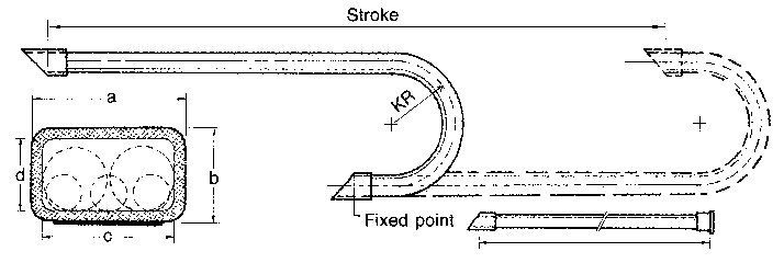
Length : fixed point in the middle - total length = stroke/2+ 3 (KR+G)
fixed point in the one side - total length = stroke + 3 (KR+G)
Model : To choose fit model, it's recommended 20% plus to the inside cable's outer diameter
Curve : To choose winding radius, it's recommended 8~10 times to the inside cable's diameter
2-3 Brackets for Snap-on Type

2-4 Product Series 1

2-5 Assembly method - Product Series 1

2-6 Product Series 2


2-7 Assembly method - Product Series 2

When assembling the cover, tilt the cover 45∘ to the connecting position and press it.


4.Chip Protection Closed Type
4-1 Chip Protection Closed Cable Chain

4-2 Dimensions for Chip Protection Closed Cable Chain

Body : reinforced plastic
Length : fixed point in the middle - total length = stroke/2 + 3 (KR+G)
fixed point in one side - total length = stroke + 3 (KR+G)
Model : To choose fit model, it's recommended 20% plus to the inside cable's outer diameter.
Curve : To choose winding radius, it's recommended 8~10 times to the inside cable's diameter.
4-3 Brackets for Chip Protection Closed Cable Chain

5.Snap-open Chip Protection Type
5-1 Snap-open chip protection Cable chain

5-2 Dimensions for Snap-open chip protection Cable chain


5-3 Dimensions for Snap-open Chip Protection Cable Chain


Design Spec.
Cable Chain Design Specification
- Speed of Travel
For unsupported application, KYEC cable chains achieve speeds in excess of 5 m/s and rates of acceleration of more than (10m/s). These guidelines apply to KYEC energy chains of every size if they are used " unsupported straight". In specific applications, the top speed is influenced and limited by the length of travel,additional load and the frequency of travel.
- Service life
In order to estimate the service life of an unsupported application, all technical data must be provided: type and number of conduits, additional load, speed, acceleration, travel frequency and details of the technical environment. Wear of the energy chains is very low, due to a special material compound and plastic-oriented design. A service life of between 15-30 million cycles can be achieved for "unsupported straight" applications even in high speed application.
- Unsupported lengths
The maximum length of travel possible of an unsupported application depends on the stability of the chain used, and on the weight of the cables and hoses inside the chain (additional load). Figure 1 shows the maximum permissible " unsupported lengths with sag (FL)" of all KYEC cable chains depending on the additional load. Unsupported length is defined here in such a way that the upper section of the cable chain has a permission sag. In this case the upper section is bent over the back.
The largest possible travel is in any case equal to twice the largest possible unsupported length:
S max. = FLB*2
S max.= maximum travel
FLB= unsupported length with sag taking the additional load into account
The sag of the KYEC cable chains does not pose a problem in many applications. It may become critical however when acceleration and frequency of travel are very high. In such cases the cable chain may be additionally supported. Figure 2 shows the conditions for the application of the chains "unsupported straight". "Unsupported straight" means that the upper section hangs parallel to the lower section. This configuration permits maximum travel speeds, accelerations and bending cycles.


Guiding trough
Guiding trough are used for long travels, figure 3 is the basic shape. Height of guiding trough should be at least double to the height of cable chains.